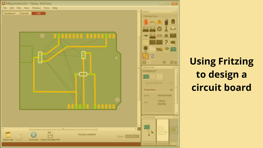
Using Fritzing to design a circuit board
Hello People. This article discusses about Using Fritzing to design a circuit board. You can design your own electronic motherboards in Fritzing.
Fritzing has a PCB View that lets you design and export layout files for single-sided, DIY Printed Circuit Boards. You can also export your sketch to Gerber files. After that you can send them to a professional PCB manufacturing service.
To switch to the PCB View in Fritzing, use the Navigator or the View Switcher. The PCB View might look a bit confusing because PCB View only shows the necessary information needed for the PCB design. This information is shown in different layers.
The first step in designing a PCB layout using Fritzing is arranging the parts on the board. Place the parts with the most connections in the middle of the board. Do not place parts too close to the edges of the board.
After positioning all parts on the board, make sure that parts are not really connected to each other yet. Click the Auto-route function from the bottom menu bar. If you notice that Fritzing is having trouble while trying to generate a connection, you can press the "Skip this Trace" button or "Cancel Auto-routing" in the bottom menu while in process.

Such a problem might happen because parts were not arranged properly on the board or when there is just no possible route. In this case, you will then need to Hand-route the trace or create a jumper. Jumpers are connections that need to be soldered with external wires.
Are you looking to start your business in the electric vehicle industry? We provide software development, web application development, mobile application development, charging stations management app, electric vehicle fleet management software development, cyber security and all software services. Please check our home page here https://iwheels.co/

Ok. Let's get back to the article.
Simply click a part's connector, and drag to make a connection. A trace will be created. To create a jumper, just right-click on the trace and choose "Create Jumper from Selected Wire(s)". You need to be cautious when moving parts. Make sure you don't create any short circuits.
You might need to edit traces by moving, adjusting width and adding bend points. Width adjustment can be done in the Inspector. Thin traces might ruin in a DIY PCB production, so please keep traces in medium thickness.
Fritzing offers a variety of export options. You can choose to export JPG, PNG, etchable PDF and even Gerber files. The Bill of Materials option generates a list of all parts in the circuit. From the menu bar choose File > Export > and the desired format. For DIY PCB production, use the Etchable PDF option which exports only the necessary design for etching. When exporting Gerber files, create a folder for the gerbers, and zip it before sending to a manufacturer.
Hope this article about Using Fritzing to design a circuit board is useful to you. Please read about Javascript Libraries for IOT projects